CNC Machining Design Guide: Maximizing Your Results

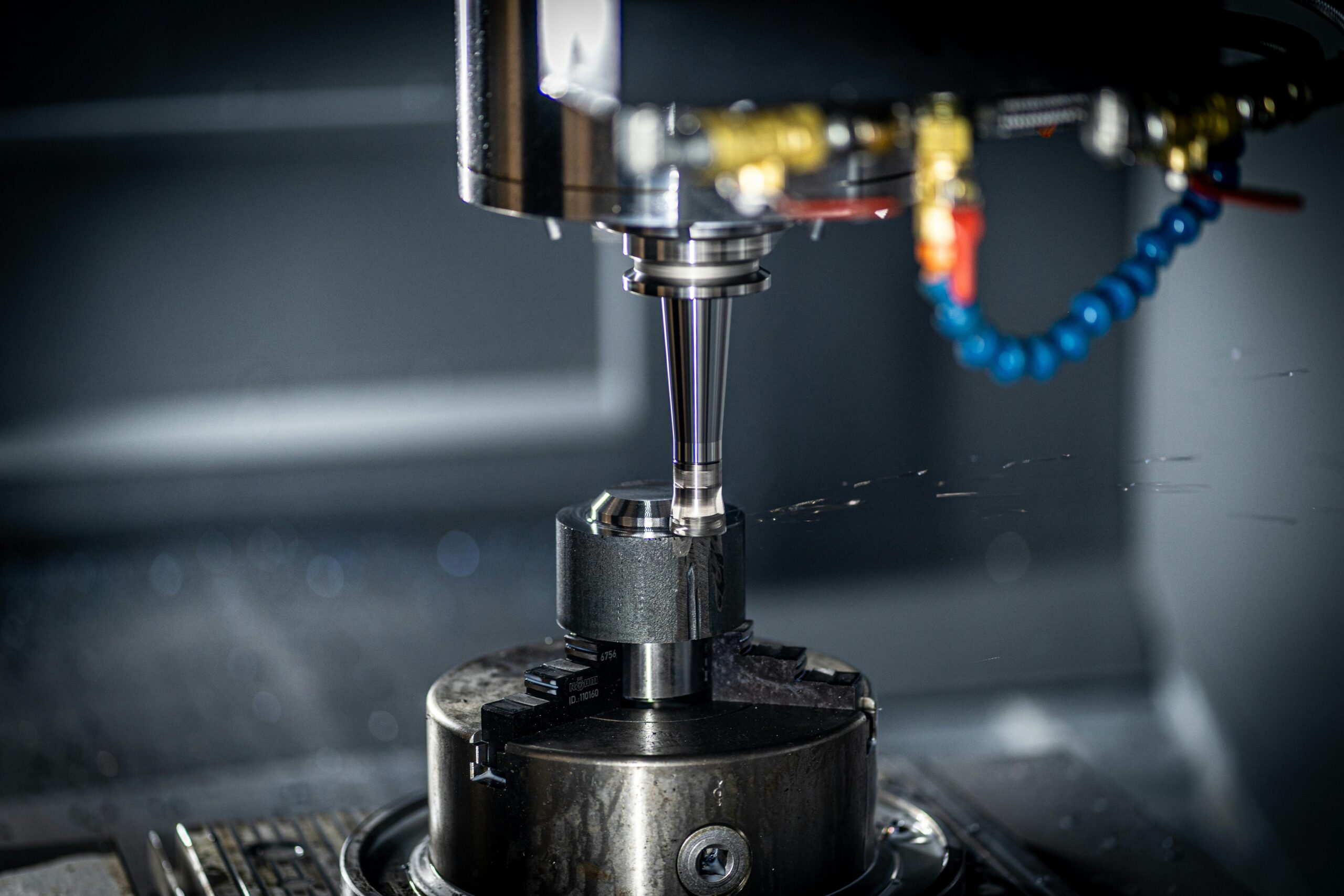
CNC machining is a versatile manufacturing process that produces various components with high accuracy and repeatability. It plays a crucial role in creating complex, high-precision components for various industries, including automotive, aerospace, agriculture, high-tech, and medical sectors.
This article will explore the essential aspects of CNC machining design. From general best practices to tailored tips for different CNC operations, we will delve into how to optimize your designs for maximum CNC performance.

CNC Machining Design Guide: Maximizing Your Results

What Is CNC Machining?

In CNC machining, the development of a part progresses from the initial concept to its physical form through a precise and advanced technological process. Initially, a CNC engineer creates the design using sophisticated CAD software. This design is then converted into G-code, which serves as the directive code for CNC machines. Following this code, the CNC machine uses specialized cutting tools to carefully shape the part from a solid block of material.

CNC machines, such as vertical and horizontal milling machines and lathes, can operate on various axes. For simpler parts, traditional 3-axis machines manipulate components along linear axes (X, Y, and Z). In contrast, 5-axis machining can operate along the three linear axes and additional rotational axes, allowing for the creation of more complex parts.

This advanced manufacturing process enables the production of high-precision and intricate parts from a variety of materials, including alumininum, steel, brass, and different plastics. Additionally, it is fast, automatic, precise, and scalable, making it suitable for applications in prototyping and mass production.

Key Considerations for CNC Machining Design

Here are some essential considerations for CNC machining design:

1. Design parts for easy machining using tools with a large diameter. This approach helps ensure faster processing and eliminates the need for specialized tools.

2. Avoid creating cavities that are more than four times deeper than their width, as this can complicate the machining process.

3. When machining text, do not use sizes smaller than 20 points to prevent mistakes in the engraved text.

4. Consider the primary direction your machine allows and its standard number of axes when creating your design to avoid complications.

Design  Restrictions for CNC Machining

CNC provides significant design flexibility, but it has some limitations. These limitations pertain to the basic mechanics of the cutting process, mainly regarding tool geometry and access to tools.

Tool Geometry

CNC cutting tools are typically cylindrical and have a limited cutting length. When they remove material from a workpiece, they create internal corners that always have a radius, regardless of the tool size.

Cutting tools approach the workpiece from above, so features that can’t be accessed this way cannot be CNC machined, with the exception of undercuts, discussed later in the article.

For optimal results, align your model’s features (like holes and vertical walls) to the six principal directions. This is more of a guideline than a rule, as 5-axis CNC systems allow for better workpiece support.

When machining deep cavities, you’ll need tools with extended reach, which can increase machine chatter and reduce accuracy. Therefore, design parts that can be machined with the largest diameter, and the shortest length possible to simplify production.

Tool Access

Tool access is a significant concern when machining a workpiece with a considerable depth-to-width ratio. This issue arises because CNC machines typically cut from above the workpiece. Therefore, it can be challenging to machine a workpiece that is inaccessible from the top. An exception to this rule occurs during undercut machining for CNC parts.

To address this tool access challenge, you can align the features of your part or component with one of the six principal directions. Additionally, using a five-axis CNC machine with a robust workpiece holding capacity eliminates restrictions on tool access.

CNC Machining Design Guidelines

There are no universally accepted standards in the CNC machining industry, primarily due to the ever-changing landscape of manufacturing and the machines in use. Here are some basic design guidelines to help ensure excellence in your CNC machining operations:

Holes

To create holes, technicians often use drill bits or end mills. It is advisable to refer to standard drill bit dimensions, measured in either metric or imperial units, when determining the diameter of holes in your design.

Technically, any hole diameter greater than one millimeter is possible. For holes that require precise tolerances, machine operators use reamers and boring equipment. It is recommended to use a standard diameter for holes that need high accuracy and are smaller than 20 millimeters.

When designing parts for CNC machining, the maximum recommended depth for any hole is four times the nominal diameter. However, depths up to 40 times this amount can also be achieved. The nominal diameter is typically calculated as 10 times the ratio.

Internal Edges

 When machining inner edges, it’s essential to maintain at least one-third of the cavity depth. Following the recommended internal corner radii allows you to use an appropriately sized tool and adhere to the suggested cavity depth guidelines.

Using corner radii that are slightly larger than the recommended values enables CNC tools to cut internal edges along a circular path rather than a 90° angle. This technique results in a superior finish and improved quality. If your part requires sharp 90° internal corners, instead of reducing the corner radius, consider adding a T-bone undercut in your CNC design.

Threads

Threads are created using taps for internal threads and dies for external threads. Taps and dies can effectively cut threads down to M2. Machinists commonly prefer CNC threading tools, as these help minimize the risk of tap breakage. CNC threading tools are capable of cutting threads down to M6.

Most of the load applied to a threaded joint is supported by the first few threads, specifically up to 1.5 times the nominal diameter. Therefore, threads longer than three times the nominal diameter are generally unnecessary.

For threads in blind holes created with taps (which apply to all threads smaller than M6), an unthreaded length equivalent to 1.5 times the nominal diameter should be added at the bottom of the hole. When a CNC threading tool is used (for threads larger than M6), the hole can be fully threaded throughout its length.

Cavities and Pockets

End mill tools have a limitation on their cutting length, so industry standards suggest that the cavity depth in any design should be no more than four times its width. If the depth-to-width ratio is lower than this, it can lead to issues such as poor chip evacuation, increased tool deflection, and vibrations.

Does your CNC design require deeper cavities? One solution to this challenge is to use a variable cavity depth along with a specialized tool.

Small or Raised Text

When machining custom parts with CNC, it’s often necessary to include serial numbers or company names on the components. It is recommended to use a font size of 20 or larger, with the text being engraved to a depth of 5 mm. Many CNC machines come equipped with pre-programmed routines for handling font text.

Although adding text can be time-consuming, it enhances the distinctiveness of the custom CNC design. Experts suggest using laser marking or electrochemical etching, as these methods are superior to embossing and remove less material from the part.

Limitations That Impact CNC Machining Design

When designing components for CNC machining, it is essential to consider specific limitations. Understanding these constraints is vital to ensuring that the final product meets the required specifications while also keeping the production process efficient and cost-effective.

Tool Shape

When considering cutting tools, it is important to take their geometry into account. Most cutting tools have a cylindrical shape and limited cutting length, which can significantly affect the final cut and its shape.

For instance, the internal corners of a workpiece will always exhibit a radius, regardless of how small the cutting tool is. This is because the geometry of the tool is transferred to the machined part during the material removal process.

Additionally, the cylindrical shape and restricted cutting length of standard CNC cutting tools, such as end mills and drills, limit their ability to machine certain features.

Tool Capabilities

A challenging part of the CNC machining process is the tool’s ability to achieve precision when machining features that have a large depth-to-width ratio. The capabilities of the tools and their accessibility significantly influence the shape of the workpiece and the difficulty of machining intricate features.

For example, deep cavities may require specialized tools, such as CNC threading tools or extended reach drilling tools, to effectively reach the bottom. This can lead to increased machine chatter and a reduction in accuracy. Consequently, factors such as the tool’s size, shape, travel distance, and other characteristics contribute to the primary design limitations of CNC machining and can impact the precision of the final product.

Tool Stiffness

In CNC machining, manufacturers of CNC machines and tools create cutting tools using materials such as carbide and tungsten. These materials possess superior properties compared to the workpiece. However, despite their high-performance characteristics, tool deflection can still occur, leading to significant deviations in design and results.

While working with general tolerances may not pose a problem, even slight tool deflection can become a major issue in highly precise jobs that require tight tolerances. This deviation caused by tool deflection can limit design possibilities and undermine the accuracy of the final product.

Workpiece Stiffness

Cutting tools exhibit exceptional stiffness and high-performance characteristics; however, they may not be suitable for certain workpiece materials that possess superior mechanical properties. The stiffness of the workpiece can lead to vibrations and deflections, which negatively affect the accuracy and precision of CNC machining operations. As a result, achieving the desired precision and accuracy with a stiff workpiece can be challenging, particularly when trying to meet tight tolerances.

Workholding

Stiffness is essential in machining because it ensures smooth and precise operations. A weak link in thechain of stiffness“—which includes the machine, tool, part, and fixture—can lead to vibrations and reduced precision. Any movement of the part during machining can result in inconsistent outcomes and deviations from the specified tolerances. A poor setup leads to low accuracy and a lack of precision, causing each machined part to differ from the others.

Workpiece Shape

The stability and success of CNC machining mainly depend on the shape of the workpiece. The geometry of the workpiece is crucial because it affects the number of processes needed and the overall feasibility of the design. Complex shapes may sometimes necessitate repositioning the workpiece during machining, even on multi-axis machines; this can lead to reduced production efficiency.

Role of CNC Design in Enhancing Manufacturability

The design of a machined component serves as the foundation for the entire manufacturing process and is crucial to the success of the final product. Design for Manufacturability (DFM) optimizes this process, making it faster, more efficient, and cost-effective. This usually involves modifying specific features that may be difficult or impossible to produce with the available equipment and materials.

Enhancing Design Integrity

Integrating CAD (Computer-Aided Design) and CAM (Computer-Aided Manufacturing) software into manufacturing processes provides significant design flexibility for modifying part specifications. This adaptability is essential for responding swiftly to changing customer demands or for making adjustments that enhance performance, quality, or cost-efficiency.

Such flexibility enables various process optimizations. For example, manufacturers can streamline tool paths, reduce the number of setups required, or improve material usage efficiency. Additionally, this integration allows for greater automation in production, which can help minimize human errors and decrease the need for repeated setups.

Cost and Time Reduction in Manufacturing

Part design is crucial for optimizing the efficiency and speed of the manufacturing process. By carefully evaluating factors such as tool selection, cutting parameters, and machine capacity, manufacturers can enhance production efficiency. This optimization can lead to reduced cycle times, increased productivity, and lower production costs.

Enhancing Production Efficiency

The efficiency of CNC machining is significantly influenced by the characteristics of the parts being machined. When parts are designed to minimize tool wear and reduce cycle times, it enhances machine utilization, ultimately leading to increased productivity and profitability. In addition to adhering to Design for Manufacturing (DFM) principles, there is a strong emphasis on maximizing material utilization, which is crucial for cost reduction and profit enhancement.

Efficient material usage plays a vital role in lowering the overall production costs. By carefully choosing the right materials and considering their properties—such as thickness and suitability for the intended design—manufacturers can achieve more effective material utilization. This approach not only minimizes waste but also optimizes production costs.

Guide to Material Selection in CNC Machining  

Choosing the right material is crucial in this CNC design guide, as the properties of the machining material will impact machinability, cost, and the overall quality of the finished part.

Metals

Metals are strong materials that are ideal for creating CNC machined parts designed to endure high stress and heavy loads. Additionally, they offer good machinability, resistance to heat and corrosion, and are versatile enough for producing components across various applications.

Some common metals used in CNC machining include:

Plastics

Plastics are commonly used in CNC machining because they are inexpensive, lightweight, and can be easily molded into complex shapes. Additionally, certain plastics, such as polypropylene (PP) and polyetheretherketone (PEEK), are resistant to chemicals, making them ideal for manufacturing parts intended for harsh chemical or corrosive environments. Some common plastics used in CNC machining include:

  • POM
  • PMMA
  • Nylon
  • PC
  • PEEK
  • PE
  • PPO

Guide to Surface Finishes Selection in CNC Machining

Surface finishes on final products can significantly impact their function, appearance, and durability. Standard finishing options for CNC machined parts include:

As Machined

The machined finish is a convenient option because it requires no post-processing. Typically, the surface of an as-machined part has a finish of around 125 µin Ra. However, tighter tolerances can be achieved by specifying a better finish of 63, 32, or even 16 µin Ra. It is important to note that as-machined surfaces may exhibit visible tool marks and may lack uniformity in finish.

Anodizing

Anodizing is an electrochemical process that produces a durable, corrosion-resistant finish on metal surfaces used in CNC machined components. This process enhances the material’s resistance to corrosion, increases hardness, improves wear resistance, and promotes better heat dissipation. Additionally, the high-quality finish obtained through anodizing makes it suitable for painting and priming.

Sandblasting

Sandblasting is a popular method used for finishing surfaces by removing materials from an object in preparation for coating. This process results in a smooth and uniform finish. Various materials can be used for sandblasting, including sand, garnet, walnut shells, and metal beads. The choice of material depends on the desired outcome and the purpose of the sandblasting, whether it’s for cleaning or as a pre-treatment for further surface finishing.

Powder Coating

Powder coating is a method used to apply a powder paint onto a component to protect it from corrosion. There are various options for powder coating, including a wide range of colors and textures. Whether you’re looking for a classic or bold appearance, powder coating offers a versatile and durable solution for your machined parts.

Hot Dip Galvanizing

Hot-dip galvanizing is a crucial surface treatment used on CNC machined components to safeguard steel from corrosion in harsh environments. We offer a comprehensive manufacturing process that serves as the ideal solution to streamline your project from design to completion.

Guide to Surface Finishes Selection in CNC Machining

Best Practices to Follow for CNC Machining Design

To ensure high product quality, follow these best practices for designing parts specifically for CNC machining based on the type of machining.

CNC Milling Design

CNC milling is a machining technique that quickly removes material from raw stock using rotary cutters to achieve a specific shape. Milling machines come in various designs, ranging from 3-axis to 12-axis configurations.

Normally Available Cutting Tools

When designing parts for CNC milling, it’s important to consider the various tools that are commonly available, such as end mill cutters. Using these standard tools can significantly reduce both costs and lead times, as they can produce the necessary features and geometries more easily.

Additionally, be mindful of standard tool sizes when creating your design. A design that includes a radius smaller than the standard tool size may lead to complications and increased costs.

Avoid Sharp Internal Corners

Achieving sharp corners with a milling tool is impossible due to the round shape of the cutting tool. When using a CNC mill, corners must have radii that are larger than the diameter of the cutter used to create them. Ideally, the diameter of the cutting tool should be twice the radius of the corner it is making.

Fillets are also necessary when a sloped or drafted surface meets a vertical wall or sharp edge. If the surface is not flat and perpendicular to the tool, a square or ball end mill will always leave material between the wall and the surface below.

Avoid Deep Narrow Slots

Long tools tend to vibrate and deflect, leading to a poor surface finish. Therefore, the maximum final depth of cut for end mills should not exceed the following ratios of their diameter: 15 times for cutting plastic, 10 times for aluminum, and 5 times for steel.

For example, when cutting a slot in a machined steel component with a 0.5end mill that has a width of 0.55″, the depth should not exceed 2.75″. Additionally, the internal fillet radius must also consider the tool diameter, so any internal radii should be larger than 0.25″.

Use the Maximum Internal Radii in Your Design

A bigger cutter equals more material removal per time, which reduces machining time and costs. Always use the maximum internal radii permitted while designing. When feasible, stay away from radii smaller than 0.8mm.

Also, make your filets slightly larger than the endmill’s radius; for instance, use a radius of 0.130″ (3.3mm) rather than 0.125″ (3.175mm). The mill will follow a smoother route, giving the surface a finer polish.

CNC Turning Design

CNC turning is a machining process that uses a lathe to create parts featuring axial symmetry and cylindrical shapes. In this process, the workpiece is held on a rotating chuck while a cutting tool shapes it to the desired specifications. This method results in improved surface finish and tighter tolerances.

Here are some tips for designing parts for CNC turning:

Avoid Sharp Internal and External Corners

When designing for CNC machining, it is crucial to avoid sharp corners, both on the inside and outside of the part. One effective method to achieve this is by adding a radius to the internal corners, which helps prevent the machining tool from running against a larger surface. Another way to minimize sharp internal corners is to slightly angle steep sidewalls. Additionally, using a single lathe cutting tool to machine contours can streamline the process, as it requires fewer steps.

Avoid Thin Walls

Just like milling, removing too much material can create undue stress on the component. Walls that are too thin can also decrease rigidity. Additionally, maintaining tight tolerances becomes more difficult with thin walls. Therefore, it is advisable to keep the wall thickness of turned sections in your CNC machining design above 0.02 inches.

Avoid Using long, thin Components

When working with long, thin pieces, avoid using them as they are more prone to spinning unevenly and can cause chatter against the tool. If you need to create a lengthy component, leave space for a center drill at the free end, and use a center to ensure the part spins straight. Additionally, as a general guideline, keep the length-to-diameter ratio at 8:1 or less.

Feature Symmetry

When machining a turned part, it is generally important for any added features to be symmetrical around the turning axis. Creating non-symmetrical geometry or features typically requires more complex machining processes and setups. Characteristics such as steps, tapers, chamfers, and curves are well-suited for turning.

However, there are times when it may be necessary to incorporate features into a turned part that are not axially symmetric. In such cases, a different machining operation might be required. Even when non-symmetrical features are needed, it is often possible to maintain some degree of symmetry.

Drilling Design

This term refers to operations that involve creating holes in workpieces. The tools used in this process typically have a conical tip, enabling them to penetrate deeply into materials during machining.

When designing for CNC drilling, consider the following suggestions:

Proper Hole Depth

Drilling should never exceed a depth of 12 times the diameter of the closest bit. This limitation is important because drill bits that are longer than this tend to lose stiffness, which affects their ability to maintain tight tolerances, and they are also more prone to breaking. If you need to drill deeper, consider increasing the hole diameter.

However, if drilling a deep hole is essential, an alternative approach is to drill from both sides of the part. Keep in mind that this method requires a second machining setup, which will increase both the time and cost of the manufacturing process.

Avoid Partial Holes

Since there is a high likelihood that the drill tip may wander, it is best to avoid creating partial holes. However, if only a portion of the hole is required, ensure that the drill axis is aligned with the material so that the component will support most of the hole.

Ensure Drill Axis Stays Vertical to the Surface

To prevent tip wander, the drill axis should remain vertical to the surface. Creating a shallow, flat-bottomed pocket on the surface of a rounded object often allows the drill to enter perpendicular to that surface. While it’s ideal to use a pilot hole to address this issue, this decision is typically made during CNC machine programming rather than during the CNC part design phase.

Avoid Drilling Through Cavities

Make sure that there are no existing cavities in the area when planning the locations of your drilled holes in your CNC design. If necessary, the drilled hole can partially intersect a cavity, but only if the central axis of the hole aligns with the cavity.

Ensure Excellent Quality with Our CNC Machining Design Services

CNC machining offers great versatility, but getting the design wrong can lead to low-quality parts. This not only results in waste but can also significantly increase CNC machining costs. Choose Enze CNC machining services for reliable results.